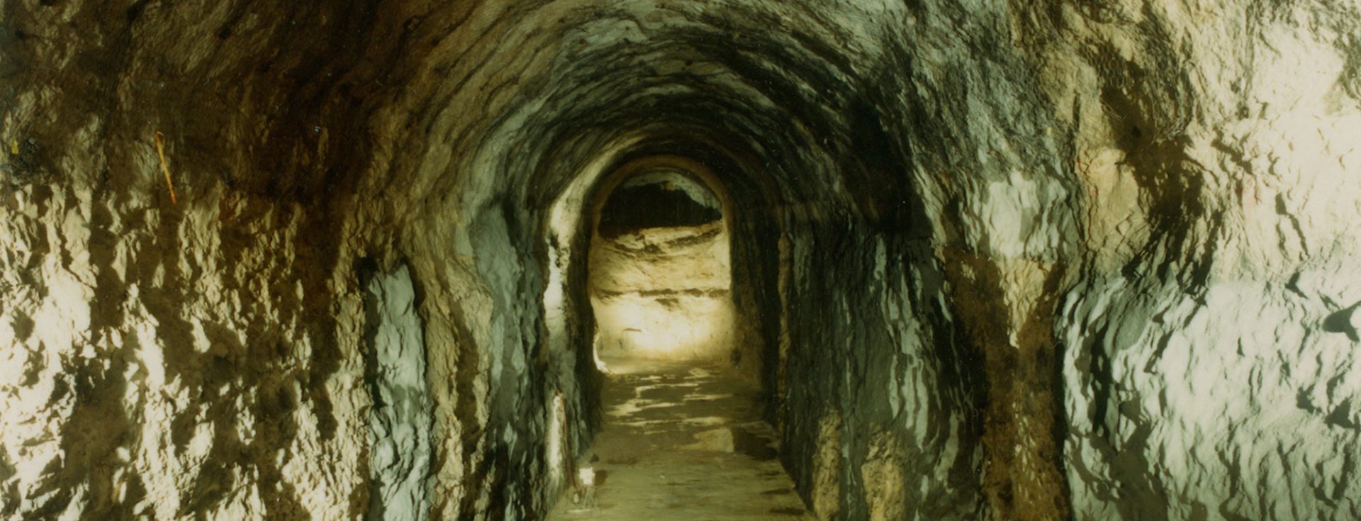
Mined hydrocarbon storage caverns were first designed and developed in the United States in the 1950s. At the time, the technology was purely mining-oriented and caverns were of the “room and pillar” type conventional in the mining industry. These underground caverns were designed to store liquid or low-pressure hydrocarbons such as LPG, using only the intrinsic sealing of the host rock to contain the product. Accordingly, geologists and engineers researched and constructed caverns in very low permeability rocky soil masses (typically with a hydraulic conductivity of less than ~ 10-8 m/s on the scale of the rock mass), such as shale or low permeability carbonated rocks, including limestone, dolomite and compact chalk, ideal for achieving this objective. The caverns were also sufficiently deep for the pore-water pressures in the rock (pressures exerted by the water naturally present in the rock) to be greater than the pressure of the stored product. This was a positive addition to the intrinsic sealing of the rock but did not necessarily fully meet the hydrodynamic containment criterion. This hydrodynamic containment criterion (see below) was not fulfilled until a few decades later.
The first LPG storage cavern built in France was developed on the basis of this concept imported from the United States in the mid-1960s by Fenix & Scisson. However, the storage capacity of this type of cavern remained modest, at around a few tens of thousands of square metres. Furthermore, owing to the use of the intrinsic sealing principle, this technique could not be developed in geological environments with substantial rock mass permeability, which is often the case.
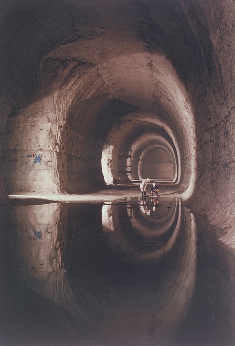
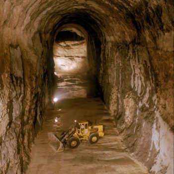
Thanks to improvements in excavation equipment and the development of rock mechanics, a new concept of large caverns for the storage of hydrocarbons in unlined mined caverns emerged, first in Northern Europe (thanks to good geological conditions) and then in France. Storage in caverns in rooms and pillars therefore mainly gave way to the concept of storage in large longitudinal galleries with cross-sections of up to 600 m2 over several hundred metres.
The hydrodynamic containment concept marked a turning point in the design of unlined mined caverns for hydrocarbon storage, making them much more adaptable to a wide variety of geological conditions, including fractured rocks, which was not the case in the previous concept. Many geological environments (sedimentary, volcanic, plutonic, metamorphic rocks) became favourable candidates for the creation of storage caverns, boosting interest in this underground storage technology.
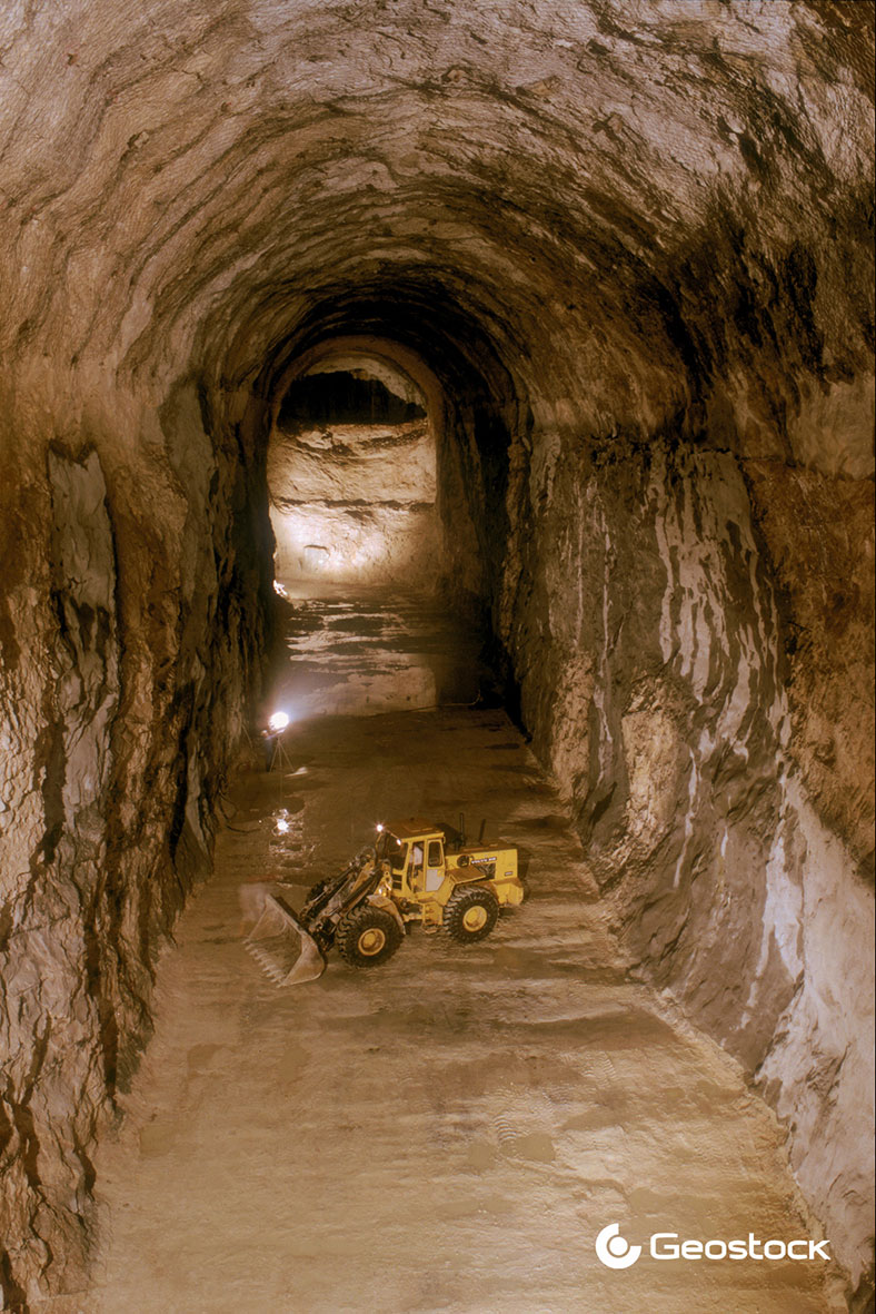
Storage cavern stability is ensured by conventional methods of support by shotcrete (preferably reinforced with steel fibre) and reinforcement through bolting (steel or fibreglass bolts) installed as the caverns excavated. The thickness of the shotcrete, the number and length of the bolts and the characteristics of the materials to be used are defined according to the geotechnical quality of the rock mass. This quality is assessed in real time as the work progresses by geological mapping and is based on proven empirical methods (for example, Q-system and RMR) for assessment purposes. In some cases, a heavier support, or even a pre-support, may be necessary (steel arches, reinforced shotcrete ribs, forepoling) to ensure the long-term stability of the galleries, particularly in fault areas or heavily fractured areas.
To limit the amount of water to be managed in underground caverns, rock grouting is carried out during excavation work in the most permeable areas.
Geostock has been involved in the vast majority of mined caverns around the world since the 1980s.
Recently, the development of lined rock cavern storage concepts has proven to be relevant for:
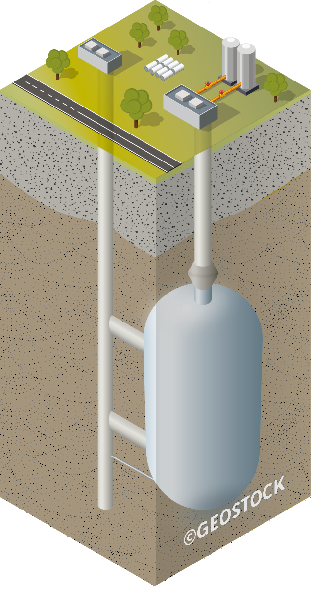
In the case of storing high-pressure gaseous products (initially natural gas, but now also hydrogen or compressed air), the maximum anticipated pressure can vary between 10 and 20 MPa depending on the rock type. The concept of hydrodynamic confinement would require prohibitively deep depths for such a pressure level in a vavern, so an steel membrane is necessary to ensure product integrity while maintaining a standard storage depth for mined caverns, typically around a hundred meters. For a given maximum operating pressure, the depth of the underground cavern is designed in a way that the pressure inside the cavity does not risk uplifting the surrounding terrain (uplift concept). The architecture of the underground storage will depend on the mass capacity required and can consist of vertical storages (such as wells or silos) for smaller or moderate volumes, or horizontal tunnels for larger volumes. Geostock is currently working on developing the most optimized techno-economic solutions for high-pressure gaseous hydrogen storage in lined rock caverns.
For cryogenic storage in lined mined caverns (such as ammonia storage or CO2 buffer storage), a lining consisting of a stainless-steel corrugated membrane ensures the containment of the product and a layer of polyurethane foam placed on a concrete wall is used to insulate the rock against thermal shocks. A drainage system consisting of a network of boreholes placed approximately 10 to 15 m under the storage galleries desaturates the rock mass before the lining is put in place such as avoid water arrival, as well as overpressure generated by the formation of ice lenses during the preliminary phase of the storage operation. The depth of storage is such that the frozen zone above the storage remains sufficiently far from the surface, the crown of the storage galleries being placed at a depth of approximately 50 m. A (liquid nitrogen) pilot cavern has been built and tested in South Korea as part of a partnership between Geostock, Saipem and SKEC, proving the feasibility of the concept and the operation of this type of storage. The concept allows for the storage of large volumes of natural gas and a low boil-off rate compared with the storage of LNG in surface tanks.
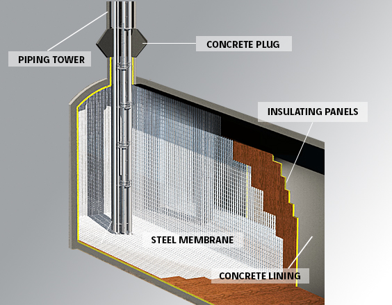
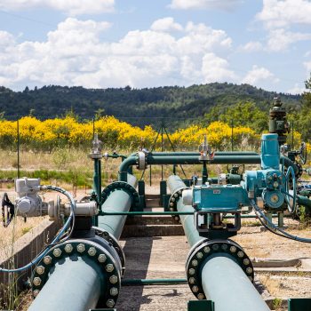
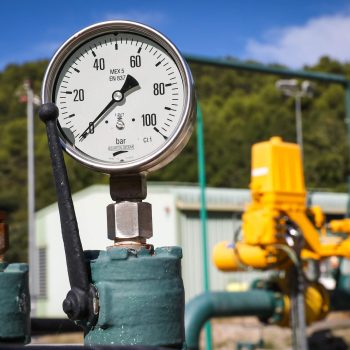
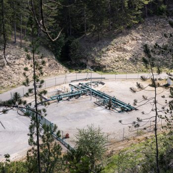
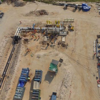
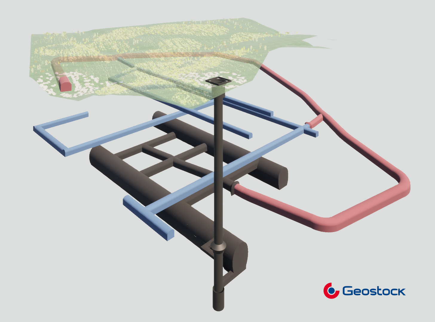
Regardless of the Lined Rock Cavern technology used, vertical pipelines are installed to allow for the circulation of stored products between the cavern and the surface. Pumps are installed at the bottom of the cavern for this purpose. In the case of an unlined cavern, it is necessary to regularly remove infiltrated water (or dewatering water). This is achieved through dedicated pumps and casings for dewatering purposes. These various pipelines, along with instrumentation lines, are typically consolidated in a large-diameter shaft.
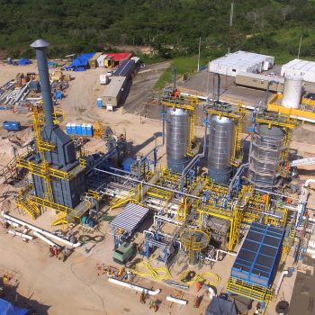
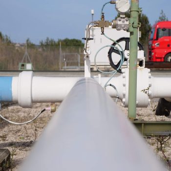
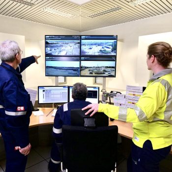
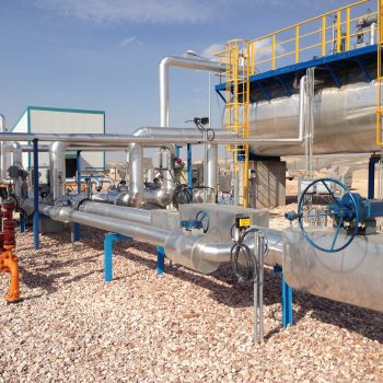
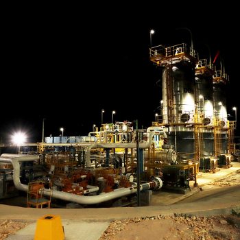
Unlined mined caverns also require facilities to treat the product before shipment and to treat the dewatering water. Surface equipment includes metering stations as well.