Friday 3 March 2023 - Publications

Hydrogen can be stored in underground caverns or geological structures in one of four ways.
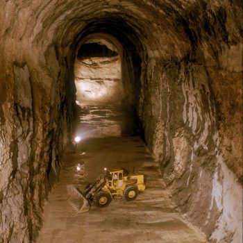
The easiest way to store hydrogen is in salt caverns. These are created by injecting fresh water or water with low salt content into a well down to a salt geological layer, with the extraction of salt-saturated brine. The caverns measure between 50 and 100 metres in diameter and up to several hundred meters tall where the salt formation is thick enough. Salt caverns are not lined, as the salt itself acts as a sealant. This type of storage is suitable for storing hydrogen at extremely high pressures where the salt layer is deep enough.
The second way to store large quantities of hydrogen is to inject pure hydrogen or a hydrogen-methane mix into porous rock, in a depleted oil or gas field, or an aquifer. The hydrogen content may vary from a few per cent to 100 per cent. Reservoir and biochemical testing/modelling are to be performed accordingly. The hydrogen-methane mix can be withdrawn and injected into the network. Alternatively, hydrogen can be separated from methane at the well head, for example using pressure swing adsorption technology.
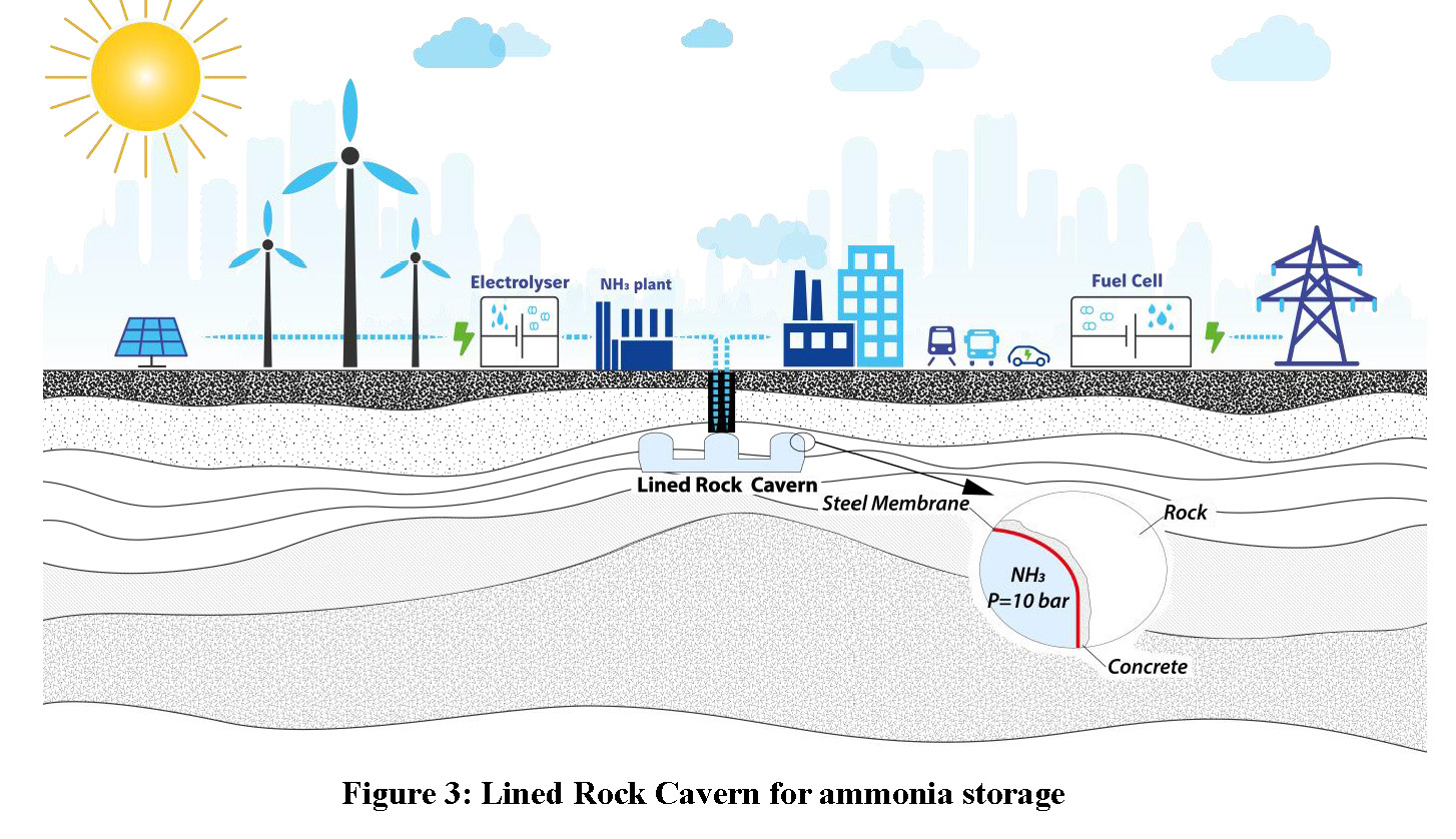
Hydrogen can also be stored underground by converting it into a liquid carrier, such as ammonia, which can then be stored in a Lined Rock Cavern. A liner is required to prevent contact between ammonia and water. The pressure and temperature are adapted to optimise the entire supply chain. The advantage of using ammonia is that proper storage conditions can be fulfilled without the need for excessive pressure or temperature.
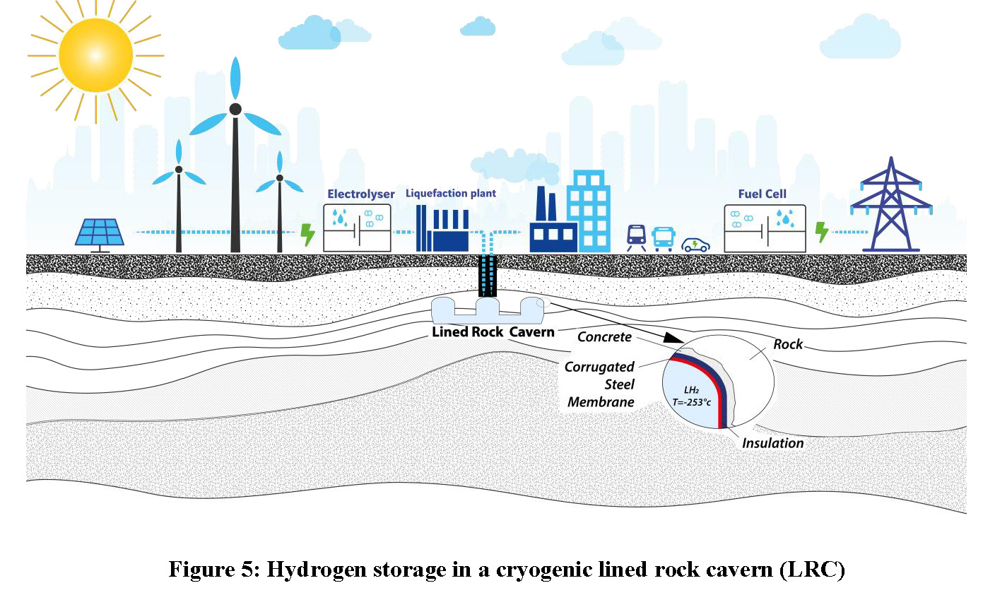
Lastly, hydrogen can be stored underground by directly injecting it into a Lined Rock Cavern. This may take the form of compressed storage (gaseous hydrogen) or cryogenic storage (liquid hydrogen), the choice once again depending on the supply chain as a whole. A liner is required owing to extremely high pressures and low temperatures. It should be noted that storing hydrogen in a Lined Rock Cavern involves a few technical difficulties that have yet to be resolved.
These four underground hydrogen storage techniques differ in terms of their technology readiness level (TRL) and cost. All four will likely be required in the coming years to satisfy the needs of a booming market.

Author
Louis Londe, Technical Director, Projects & Innovation, Geostock
Hydrogen has been identified as an energy carrier that could play a major role in decarbonisation, and green hydrogen is seen as a possible substitute to fossil fuels. A number of governments and institutions have announced ambitious plans for developing a hydrogen economy, with the European Community having set a 2030 target of 40 GW of electrolysers producing 10 million tonnes of renewable hydrogen (European Commission, 2020). Similar plans exist in other world regions.
These substantial quantities of hydrogen will require storage capacities. Whether these storage capacities will be scattered or centralized remains an open question, but many analysts consider that large and centralised storage units will be needed.
Underground storage is likely to be the best solution for fulfilling extensive storage needs (Jens, 2021) as it boasts numerous advantages in terms of environment protection, safety and, above all, CAPEX (for high storage capacity) and OPEX.
The various methods for the underground storage of hydrogen are described below, from the easiest to the most challenging.
Salt caverns are a proven technology for storing hydrocarbons (Londe, 2017), including natural gas, liquid hydrocarbons such as crude oil or refined products, and liquefied hydrocarbons such as LPG. More than 1,900 salt caverns exist worldwide.
Salt caverns are created by solution mining, i.e. by injecting fresh water or sea water into a deep well. Creating a volume of one requires the injection of eight to ten volumes of water. Solution mining is also referred to as the “leaching” process. In direct leaching, fresh water is injected through a central tubing and saturated brine is withdrawn through the annular space. Reverse leaching consists in injecting fresh water into the annular space and withdrawing saturated brine through the central tubing. Cavern shape is controlled by positioning the tubing, adapting the water flow rate and selecting direct leaching or reverse leaching. Cavern dimensions are to be adapted to the requirements of the owner and the characteristics of the salt layer. Cavern heights greater than 300 metres are common practice, while cavern diameters are generally between 50 and 100 m. A large variety of sizes exist, ranging from 50,000 m3 to more than 1,000,000 m3. Creating a 500,000 m3 salt cavern takes between six months and two years.
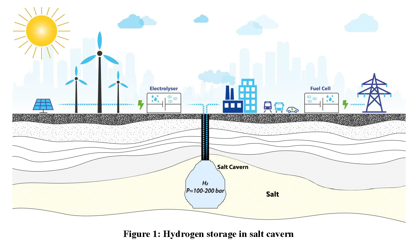
The operating pressure depends on cavern depth. If the cavern is deep enough, say more than 1,000 m deep, operating pressure can exceed 200 bar. A minimum pressure is required to prevent salt damage and cavern closure by excessive visco-plastic behaviour (referred to as “salt creep”). The gas inventory at minimum pressure is the “cushion gas”, which represents approximately one third of the total gas.
Salt caverns were first used for hydrogen storage five decades ago in the UK, the first such cavern being commissioned near Teesside in 1972. Three caverns have been built on this site for a total amount of approximately 2 Mm3, at a depth of 400 metres, with an operating pressure of around 50 bar (Lindblom, 1985).
Since then, only six salt caverns have been built for hydrogen storage, all of them in the USA (Moss Bluff, Clemens Dome, Spindletop) and in the UK (Teesside). These hydrogen storage facilities are all devoted to the chemical or petrochemical industry, the hydrogen molecule being used for its chemical properties. The current trend is to use hydrogen for its high energy density, with various salt cavern projects having been launched recently to store hydrogen as an energy carrier. There is obviously no technical showstopper to create salt caverns for hydrogen. Indeed, existing hydrogen caverns demonstrate:
Nevertheless, a few specific items deserve attention and explain why some of the new projects are presented as demonstrators, including:
Porous rocks, either in depleted fields or in aquifers, have been used for storing natural gas for over a century. The first underground storage for natural gas was built in the USA in 1915 (Londe, 2017).
Unlike salt caverns, porous rock storages use natural voids. Porosity is often encountered in sedimentary rock such as sandstones or fractured carbonates. Owing to its low density, the gas is entrapped within a geological structure. This structure is generally an anticline covered by an impervious caprock (clay, claystone, etc.). The volume of stored gas is such that it never reaches the “spill point” of the structure.
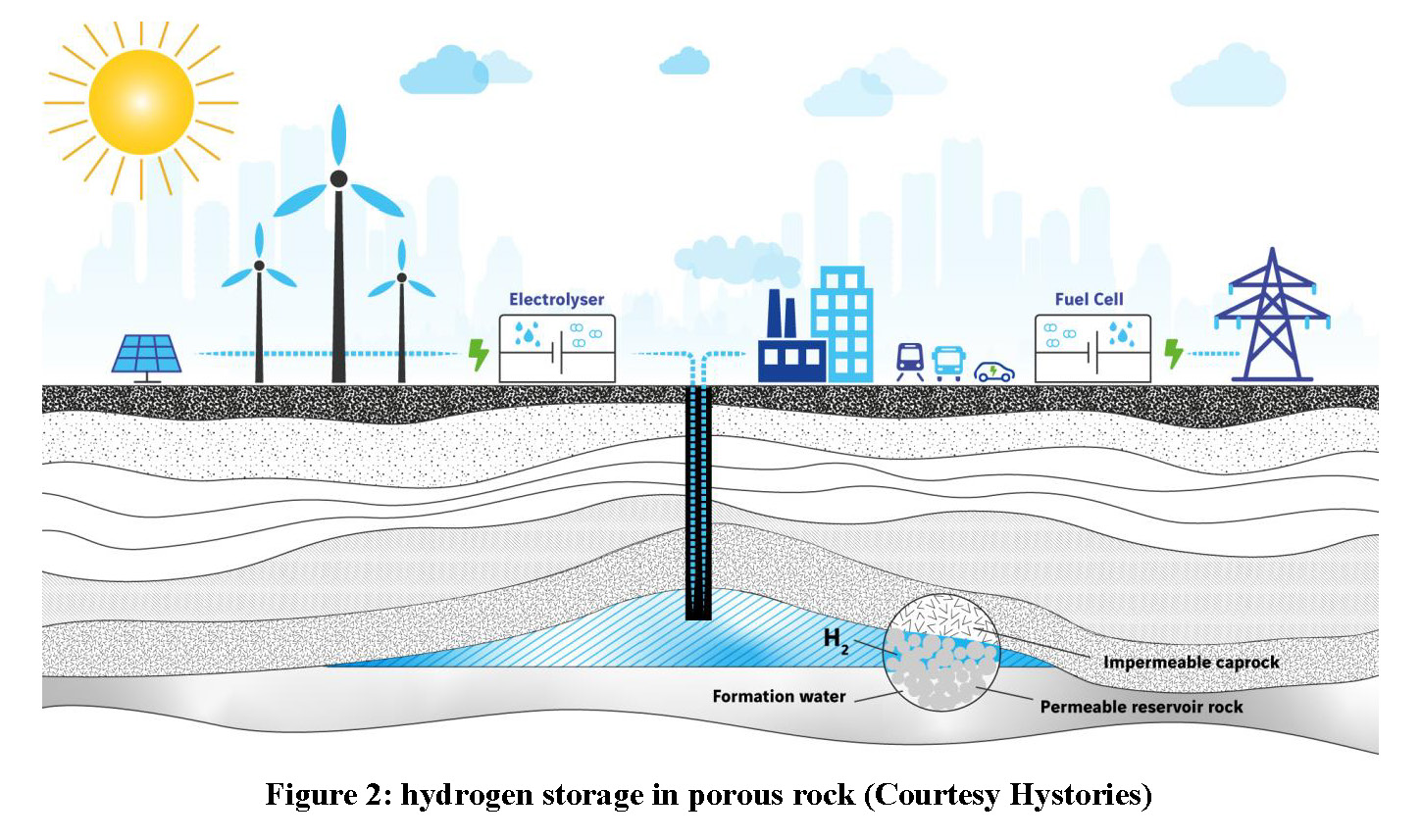
Wells are drilled to inject and withdraw the gas. Other wells are dispatched above and around the structure to check the tightness of the system. Operating pressure is set based on theoretical considerations and track records where available. Pressures as high as 200 bar are common practice. As in salt caverns, but for other reasons, some of the injected gas remains entrapped in the storage as “cushion gas”.
Storing hydrogen into porous rock first takes place as a blending of natural gas (i.e. mainly methane) and hydrogen. It is important to highlight that this has been done in many places in the past. Town gas, also referred to as water gas or manufactured gas, often containing up to 50% hydrogen, has been stored in various underground storage facilities, in depleted fields or aquifers (Marcogaz, 2017). These town gas underground storage units were decommissioned or converted into natural gas storage in the 1950s.
Name
|
Storage Type
|
Owner
|
Status
|
|
Engelbostel (Germany) |
Aquifer |
Formerly Ruhrgas |
Decommissioned |
|
Bad Lauchstadt (Germany) |
Porous rock |
VNG |
Now used for natural gas |
|
Hähnlein (Germany) |
Aquifer |
MND Storage |
Now used for natural gas |
|
Eschenfelden (Germany) |
Aquifer |
Uniper |
Now used for natural gas |
|
Kirchheiligen (Germany) |
Depleted field |
VNG |
Now used for natural gas |
|
Ketzin (Germany) |
Aquifer |
Formerly VNG |
Decommissioned |
|
Lobodice (Czech Republic) |
Aquifer |
RWE |
Now used for natural gas |
|
Beynes (France) |
Aquifer |
Formerly Gaz de France |
Now used for natural gas |
The gas industry is currently launching research programs and pilot plants to provide scientific evidence that the town gas experience can be repeated as part of a controlled and documented approach.
Items to be investigated include (Heinemann, 2021):
Most of these items are currently addressed by various R&D programmes, such as the Sun Project managed by RAG in Austria (Bauer, 2017). Hystories, financed by FCH-JU, is another R&D programme grouping most of the European gas industry players, including research institutes and gas infrastructure operators.
Research results are encouraging:
Hydrogen can be transported in its gaseous state in pipelines. This will be probably the preferred means of transport over long distances in integrated and continental regions such as Europe or North America. Salt caverns and porous rocks will find a natural place within pipeline infrastructures for gaseous hydrogen transport.
It is also very likely that ships will be used for the intercontinental transportation of hydrogen. Hydrogen tankers could transport liquid hydrogen (LH2) at very low temperatures (-253°C). Hydrogen has a much higher density in its liquid state than in its gaseous state, generating substantial savings for long-distance sea transport. However, R&D efforts are still required to design a containment system (insulation and membrane) for temperatures this low, and liquefaction costs are considerable.
A promising alternative is to use molecules containing hydrogen, providing that the molecules are easy to liquefy. One such molecule is methylcyclohexane, an organic chemical hydride that liberates H2 when transformed into toluene. Methylcyclohexane is a stable liquid at ambient pressure and temperature.
A popular hydrogen liquid carrier is ammonia (NH3). Ammonia is liquid around 30°C at a pressure of 10 bar and around -40°C at atmospheric pressure. This makes it easy to liquefy for transport purposes. Today, ammonia is stored in pressurised spheres (20°C, 10 bar) or semi-cryogenic spheres (0°C, 4 bar) up to 5,000 m3 capacity. For larger capacities, ammonia is also stored in cryogenic tanks (-33°C). Underground storage is another possibility, one that could offer all the advantages of underground storage where salt is not available.
Ammonia could be stored in hard rock caverns in almost any kind of rock providing that it is strong enough to be excavated without heavy support. Most reasonably weathered or fractured rocks would be eligible, either sedimentary (limestone, sandstone, etc.), magmatic (granite, basalt, etc.) or metamorphic (gneiss, mica schist, etc.). This considerably broadens the range of potential locations relative to salt caverns.
However, the underground storage of ammonia is not straightforward, as ammonia has a high affinity with water and the dissolution of ammonia in water is highly exothermic (2,000 kJ/kg of ammonia). Consequently, ammonia needs to be isolated from water. In hard rock caverns, this would require the use of a steel liner.
These “Lined Rock Caverns” (LRC) are feasible with a limited R&D effort. The LRC concept was demonstrated in 2004 in Sweden for natural gas with a pressure higher than 200 bar and for fast cycling conditions (Sydkraft AB, 2004). There should not be any significant difficulty for ammonia around a few tens of bars. Here, we are considering a pressurised LRC at ambient temperature. Alternatives at lower pressure and lower temperature, say between 0°C and -40°C, are also feasible.
The fourth hydrogen storage technology is the Lined Rock Cavern, directly as hydrogen rather than as a transformed molecule such as ammonia. Two different options are to be considered:
Options 1 and 2 generate different challenges. In both cases, these challenges are greater than for ammonia LRC, owing to high pressure (option 1) or very low temperature (option 2). But both options are advantageous in terms of environmental protection and safety, and may prove economically attractive for large capacities.
Let us first consider a pressurised LRC (option 1). Owing to its low density, hydrogen cannot reasonably be stored at low pressure. A 100,000 m3 cavern operated at 10 bar would yield a capacity of less than 90 tonnes of hydrogen, which substantially diminishes the interest of underground storage. Pressures of around 100 or 200 bar will therefore be the target. But the question here is whether a mined cavern is adapted to a 100 or 200 bar operating pressure. The answer is yes, under certain conditions.
LPG and liquid hydrocarbons are stored around the world in unlined mined caverns. However, a pressure of 100 or 200 bar would require building an unlined rock cavern at a depth of 1,000 m to 2,000 m. Unlined rock caverns must fulfil the Hydrodynamic Containment Principle which requires a water head higher than the operation pressure (Aberg, 1975; Van Hasselt, 2003). Sinking a shaft or digging an access tunnel to reach 1,000 m or 2,000 m is not realistic. Alternatively, an over-pressurized box-type water curtain may be used to govern hydraulic pressures around the cavern, thus allowing a shallower depth (Lindblom, 1985). While theoretically feasible, this option is rather risky for various reasons, including clogging owing to high water flow, as well as high water consumption and difficulties in tunning water curtain dynamic pressure.
A liner is therefore highly recommended. The LRC depth will depend on the rock quality. Even with the presence of a liner to ensure hydrogen tightness, the operating pressure will need to be controlled to avoid high deformation of the rock mass and of the liner itself. Moreover, operating pressure remains linked to the cavern depth though the notion of uplift. Uplift occurs when the pressure is so high that it lifts the overburden up, ruining the liner. A stiff rock at a relatively great depth, say 100 m or 200 m, will allow pressures as high as 100 or 200 bar.
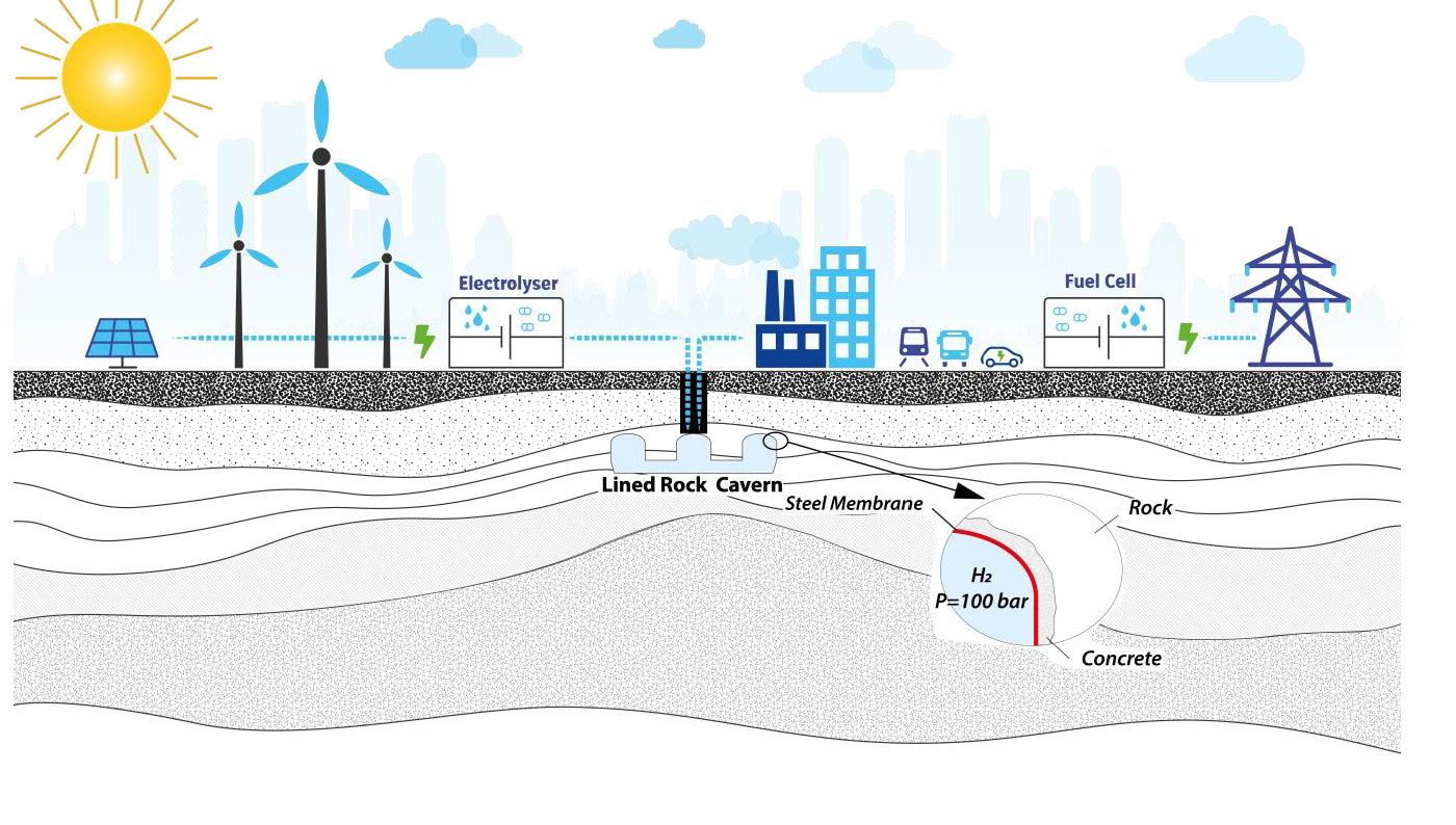
The feasibility of such an LRC for pressurised hydrogen has been confirmed by the Skallen project, in which pressures of higher than 200 bar have been reached with success (Sydkraft AB, 2004). Fast cycling has also been tested at Skallen, at 30 bar to 200 bar, back and forth, for 12 hours over a period of a few weeks. However, Skallen was a natural gas demonstrator. A specific demonstration could be proposed for hydrogen in order to address the issues below, none of them being a potential showstopper:
Let us now consider a cryogenic cavern for LH2. A similar concept has been developed for liquefied natural gas (LNG) by Geostock, SN Technigaz (then SAIPEM) and SKEC (Londe, 1993). A pilot was built and operated with success in Taejon, South Korea, in 2004 (Amantini, 2005).
The principle of the cryogenic cavern is rather simple. It combines two proven technologies: the rock cavern commonly used for LPG and liquid hydrocarbon storage, and the containment system used in LNG tankers and LNG tanks. The containment system is based on the Mark III patented system currently owned by GTT. Tightness is ensured by a steel membrane, which is corrugated to sustain thermal deformation. Insulation layers are installed behind the steel membrane, protecting the rock mass against thermal shock. This insulation also reduces the initial boil-off rate. The insulation layers also comprise a second tightness barrier. The full liner, composed of the steel membrane and the insulation layers, is anchored on a concrete wall.
Adapting this LNG cryogenic cavern to hydrogen storage will require R&D studies as the temperature of LH2 (-253°C) is lower than that of LNG (-162°C). The insulation will thus need to be optimised and the welding of the steel plates will need to be adapted to subsequent very low temperatures. Last but not least, the steel quality will be governed by welding, temperature and hydrogen embrittlement constraints.
Hydrogen demand today is driven by three main uses: industrial decarbonization, carbon-free mobility and power generation.
Although decentralized, hydrogen storage for industry feedstock will justify large capacities. Paving the way is the Hybrit project, aimed at producing fossil-free steel in Sweden (Bränneberg Fogelström, 2020), and in which the underground storage of hydrogen is foreseen. Further projects will arise for other greenhouse gas-emitting industries.
At first glance, hydrogen storage for mobility appears to be decentralised. But in a world where hydrogen cars are used by many customers and voters, manufacturers and politicians will not take the risk of a hydrogen supply crisis. Massive hydrogen storage capacities will be built to buffer decentralised storage capacities. Again, underground storage will be a solution, and probably before 2030.
Hydrogen for power-to-power will emerge only when intermittent renewable energies exceed a threshold percentage within the energy mix. This percentage depends on regional specificities. Hydrogen storage for power generation could take place in 2040 or later, depending on power network interconnexions.
The large-scale storage of hydrogen will therefore be required to satisfy industry, mobility and power-to-power needs. Underground storage in salt caverns will be the preferred solution since it offers significant cost savings and flexibility. A 100,000 m3 salt cavern would have a storage capacity of approximately 700 tonnes of hydrogen, the exact capacity depending on cavern depth. Salt caverns of 300,000 m3 and 600,000 m3 could store 2,000 and 4,000 tonnes of hydrogen, respectively. These values are to be compared with surface storage capacities, as a large liquid hydrogen sphere contains only 200 tonnes.
For very large quantities, or for methane-hydrogen blending, porous rock will be an attractive alternative, as storage capacities in porous reservoirs are generally substantial. For example, the UK North Sea Leman field has a theoretical hydrogen storage capacity of 833 TWh (Hassanpouryouzband, 2021). This corresponds to 25 Mtonnes of hydrogen, i.e. the capacity of more than 6,000 large salt caverns.
The number of salt caverns to be built for hydrogen storage can be assessed based on official announcements on hydrogen plans. For example, the European Community target for 2030 is 40 GW of electrolysers producing 10 million tonnes of renewable hydrogen (European Commission, 2020). Similar ambitious hydrogen plans are being launched around the world. According to the Hydrogen Council, 90 GW of green hydrogen will be produced worldwide in 2030 (McKinsey, 2021). In its 2020 Hydrogen reports, IEA estimated that 8 Mtonnes of low-carbon hydrogen will be produced in 2030 (Bermudez, 2020). Assuming that only 5% of this hydrogen is stored in salt caverns (though the percentage will likely be higher given natural gas statistics, as approximately 10% of natural gas consumption goes through underground storage worldwide, and as much as 20% in Europe), some 200 to 600 salt caverns will be built worldwide by 2030.
Barring new design standards, CAPEX for hydrogen salt caverns and hydrogen porous rock reservoirs should remain similar to that for natural gas underground storage. Mined cavern solutions will be more expensive than salt cavern solutions, as the drill and blast excavation method is unable to compete with the salt mining leaching method. Liners will also generate additional costs, both in procurement and installation. As such, the costs of a pressurised hydrogen or ammonia LRC are expected to be 50% to 100% higher than the costs of an unlined rock cavern, while the costs of a cryogenic hydrogen LRC are expected to be 100% higher than those of an unlined rock cavern.
Large-scale hydrogen storage is required to face future challenges in terms of energy and the environmental transition. Hydrogen will be used primarily for industrial decarbonisation, carbon-free mobility and carbon-free power generation. It will be used initially to decarbonize industry and mobility, for which underground storage will be required within a couple of years. Underground pure hydrogen storage for power generation will also emerge, but large-scale demand may come later, in all likelihood after 2040. Meanwhile, the gas and power generation industries will use a methane-hydrogen mix, well before 2040. The methane-hydrogen mix will gradually reach 20% hydrogen, and possibly more, and will be stored underground, mainly in porous rock reservoirs.
Salt caverns will probably account for the largest share of underground storage needs, followed by porous rock reservoirs, especially for methane-hydrogen mixes. When the technology is ready, mined caverns will find their place in the value chain for international trading (ammonia, liquid hydrogen) or where pure hydrogen is to be stored in places without salt.
R&D efforts vary for these various techniques. Salt caverns and porous rock reservoirs are ready for commercialisation, current research being aimed at furthering our knowledge and establishing standards. Demonstrators may be required here and there to address specific local questions and satisfy local decision makers, but no showstoppers have been identified overall.
Mined cavern techniques – for pressurised hydrogen, pressurised substitutes (such as ammonia) or liquefied hydrogen – will require a few years of technical developments. The corresponding caverns will be lined. Lined Rock Caverns (LRCs) for pressurised hydrogen or pressurised ammonia could be ready for commercialisation in the near future. LRCs for liquid hydrogen present greater challenges owing to the very low temperature involved (-253°C).
These mined cavern techniques will remain more expensive than salt caverns and porous rock reservoirs. However, owing to their geological adaptability, mined cavern solutions will be needed to complete the hydrogen storage portfolio.
Part of the work described in this article has been funded in part by the Hystories project. This project has received funding from the Fuel Cells and Hydrogen 2 Joint Undertaking under grant agreement No. 101007176. This Joint Undertaking receives support from the European Union’s Horizon 2020 research and innovation programme and Hydrogen Europe and Hydrogen Europe Research.